This series' hardware architecture post covered the three hardware variants (external/ integrated PHYs), and the hardware deep dive covered the external PCB interfaces. Both deliberately stayed outside the chip boundary. This post — analogous to the EthTrcv PHY architecture post — actually goes into the silicon: what happens internally when a frame passes through the switch?
Unlike the AUTOSAR APIs covered in the rest of this series, a switch chip’s internal microarchitecture is not part of the AUTOSAR SWS — it’s vendor IP. This post therefore describes generally applicable architecture principles known from networking hardware, present in some form in practically every automotive switch chip, without claiming to reproduce any specific chip exactly. |
Block overview
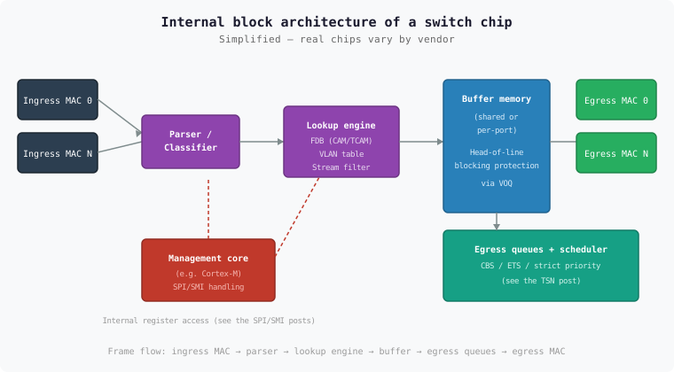
Switch fabric architectures at a glance
| Architecture | Basic idea |
|---|---|
Shared-memory switching | All ports share a single, fast memory block. Incoming frames are written to memory once; the lookup decision only determines where the egress logic reads from. Simpler to build, but the shared memory becomes a bottleneck as port count/bandwidth grows |
Crossbar switching | A matrix of switches connects every input directly to every output. Higher throughput is possible since parallel paths exist, but control is more complex and it uses more silicon area |
Many automotive switch chips with a modest port count (4–8 ports) use shared-memory architectures for cost reasons; higher-port-count or multi-gigabit chips for backbone applications tend towards crossbar or hybrid approaches.
The lookup path of a frame in silicon
Ingress MAC — receives the frame electrically/physically from the port (see the hardware deep-dive post)
Parser/classifier — extracts header fields (destination MAC, VLAN tag, EtherType, possibly the IP header) for the subsequent lookup stage
Lookup engine — elsewhere in this series (e.g. the hardware architecture post) informally also called the "forwarding engine" — looks up the destination MAC address in a CAM/TCAM-like memory structure (the software-side view of this is the ARL table, see the ARL table post), checks VLAN membership, and applies any stream filter rules (see the TSN stream post)
Buffer — the frame is held until the egress logic picks it up
CAM (Content Addressable Memory) and TCAM (Ternary CAM) are memory types addressed "backwards": you feed in a value (e.g. a MAC address) and get back the memory location (or directly the associated data, like a port number) — in a single clock cycle, regardless of table size. That’s exactly what makes line-rate lookup at millions of frames per second possible in the first place. |
Buffer architecture and head-of-line blocking
A naive approach — a single FIFO queue per ingress port — suffers from head-of-line blocking: if the frame at the front of the queue is headed for a congested egress port, it blocks every frame behind it, even if their destination ports are free.
The common remedy is Virtual Output Queuing (VOQ): instead of one queue per input, a queue is conceptually maintained per input-output pair. A congested egress port then only delays the frames actually headed for it — not the entire ingress queue.
The |
Queues and schedulers as silicon blocks
Egress queues are implemented in hardware as dedicated memory areas with associated scheduling logic — typically several queues per egress port (one per traffic class), controlled by the egress scheduler. These are exactly the blocks described in this series' TSN post as cascadable port schedulers with CBS/ETS algorithms.
The embedded management core
Many automotive switch chips contain a small embedded CPU core (often an ARM Cortex-M-like microcontroller) that:
accepts SPI or SMI register accesses from the outside and maps them internally onto the actual fabric hardware (see the SPI post and SMI post)
loads the configuration from an external EEPROM/flash at boot, before the host even starts calling
EthSwt_Initin some chip families, actually performs the software MAC learning mentioned in the SWS (see the ARL table post) instead of leaving it purely to the hardware lookup engine
This management core is not an AUTOSAR concept — it’s pure chip
internals, invisible to the |
Per-port MAC blocks
Each port has its own MAC block implementing the layer-2 framing logic
(preamble, FCS check, inter-packet gap) — regardless of whether an
embedded PHY or an external EthTrcv chip connected via MII/MDIO sits
behind it (see the
hardware
architecture post for the three hardware variants).
Summary
| Aspect | Key takeaway |
|---|---|
Fabric architecture | Shared memory (simpler, port-count limited) vs. crossbar (higher throughput, more silicon cost) |
Lookup engine | CAM/TCAM-like hardware for line-rate address/VLAN/stream lookup in a single clock cycle |
Buffers | Virtual output queuing as the standard solution against head-of-line blocking |
Management core | Not an AUTOSAR concept, but often the real instance behind
|